Lap Tracker
Published on the Internet is a lot of directions, but unfortunately nowadays, when computers have serial and parallel port, these instructions have already unworkable. Before he managed to put functional timekeeping on the old slot car ITES I found myself very much at a stalemate.
Forget converters USB – Parallel, USB – port serum because they do not work. It even failed to deploy Lap Timer 2000 on the old PC that had a serial port. But what works reliably:
- Applications for mobile Lap Tracker – a big advantage is low cost
- Old PC parallel port, a phototransistor switch and program Ultimate Racer
- PC with USB, phototransistor as a switch, electronic kits Arduino UNO program and Race Coordinator
That last option will be given to the following instructions.

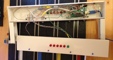
Ramp with starting lights on the slot cars
Principle

Diagram lap timer
Incident radiation phototransistor opens and with a current depending on the radiation. Thus the passage cars will reduce the radiation incident on the phototransistor anásledně and current change. To increase the sensitivity and suppression of ambient light for example, when the phototransistor is a phototransistor sun illuminated LED.
Slot car lap counting Arduino UNO and Race Coordinator
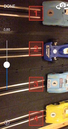
Sensors for lap counting
The advantage of this solution is a combination of several functions. The aforementioned function of measuring the number of laps and time are also starting lights START / STOP button and the light indicating the race leader. Unfortunately, the last function failed to meet expectations, so do not recommend it. The Gate can be seen in the next few videos.
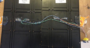
I will not describe the exact method of installation, but you can be inspired by the following figures. Importantly diagram.
Setting Arduino UNO
It’s really very easy to see the site of the product and detailed instructions on the pages http://robodoupe.cz/2011/jak-zacit-s-arduinem/. However, the most important is loaded into the kit Arduino UNO lapCounter.ino file that is located in the folder where you nmainstalovali Race Coordinator. By default this is C: \ Program Files (x86) \ Race Coordinator official \ data \ Arduino \ lapCounter \.
Setting Race Coordinator
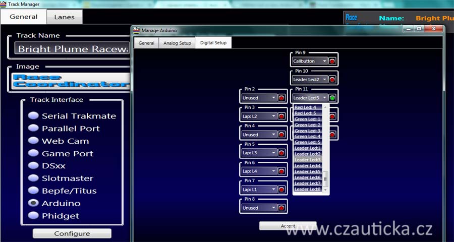
Setting Race Coordinator
Race Coordinator is a program that allows measuring wheels, time, the orchestration of entire races and tournaments. Just a little bit more I liked just Ultimate Racer, especially graphics processing. Regarding functions are the two programs as well. Among others have entrance to a parallel and serial port. The main reason why he was elected Race Coordinator is that it includes an interface for Arduino and has written a program for Arduino. Among others internment Web camera, but that I was not paying. Perhaps there will be other programs to interface to Arduino, but I did not find it. In the event that you will write to me. I like to watch them closely.
The site www.racecoordinator.net download the program and install it on your PC. The menu Race Program Coordinator, set individual inputs and outputs Arduino. The road is Menu / Track Setup / Arduino. On analogue are assigned starting light. On digital sensors are assigned. Correct assignment of LEDs to check the red button, which turns green and the corresponding LED lights. You can in case of incorrect wiring tangle of wires, diodes and fototrazzistoru reconfigure inputs without damage to wiring.
Shielding
During testing there was a problem with spontaneous Arduina disconnecting from the PC. Disconnecting cause interference to the motor cars.
Measuring wheels and racing track time on Arduino UNO and Race Coordinator
Solution:
- All power including light emitting diodes connected to the USB
- Rail track to connect the capacitor 1n
- Stabilizing capacitor 5 micro F to 5 V power supply Arduino
- All cables leading to the Arduino threaded through the choke
- Ground the unused inputs on the Arduino
- Aluminum foil to wrap the whole electronics including cables and the grounded – I did not realize.
The problem of interference may not always occur. Rather, it occurs in the original Arduino. Perhaps a more sensitive inputs.
List of components:
- Designers Arduino UNO,
- LEDs starting lights (green and red)
- LEDs to illuminate the phototransistor
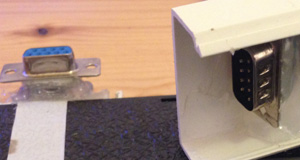
Connector
- Phototransistors – no matter if IR or classical, operate both types, I recommend you to choose smaller housing
- Gateway connector panel RS 232
- Microswitch
- Resistors – according to the used diodes. The internet is a simple calculator that will calculate the amount of resistance
- Transistors – to strengthen the performance for each output Arduino connected transistor as an amplifier
Material:
- Fusion gun
- Electricity rails
- Screws